Wednesday, 9 April 2014

Fixed rotator

What's on today:
  • Fixed rotator.
  • Fixed rotator with steps.
  • Quick look at vector graphics textures in after effect.


Fixed rotator.


How to rotate a texture by a certain fixed angle?
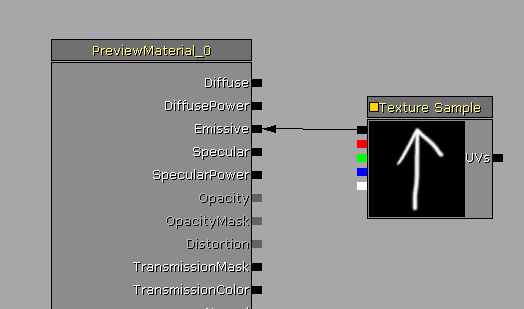
Just input a constant value in the time pin of your rotator. The constant value is like saying ‘this is where the rotator would get you in that much time’. (I mean, not technically since the unit is not seconds but it's sort of a way of seeing it.)

What to expect from that value? First thing, set your rotator speed to 1. Then you have to know that unreal uses radians as a rotation unit.
180 degrees = π (pi, the maths symbol equal to 3.14159 and so on).
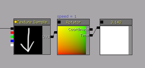
Therefore, 90 degrees is going to be π / 2.
Good thing to know: you can do maths in input fields. In your constant input, you can simply type in 3.14159/2.
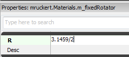


Usage.


You could use a fixed rotator to represent a circular gauge for instance. Most likely, the gameplay code is going to provide you with some normalized parameter. (Frankly that’s the best option. Sure modifying the value to fill your needs will add a few instructions but it gives you the flexibility to easily do anything you want with it, rather than having to go bug a coder so he changes the value he's hard coded for you.)

Modify the input to the range you are interested in (say 0 to 90 degrees), plug it into the rotator, and then into a mask that multiplies your gauge.

You’ll notice that I’ve just multiplied my normalised value; since my min is 0, I don’t need to use a lerp which would add more instructions for the same result.


Fixed rotator with steps.


We can go one step further.
In Enslaved, Trip has an emp gauge which recharges over time and is split in several chunks which appear one at a time.


I used a similar setting, with a rotating mask that multiplied my texture, only this time the rotation value had to be contained until it reached the next step.

In the following example our gauge value is at 0.5, that's half filled. The gauge is split into 5 chunks, so each step is 0.2.

We check: our many steps are there in our current value ? That's 0.5 / 0.2 = 2.5. We're only interested in full steps so we floor it.
We've then got two full steps, the step size is 0.2 that's 0.2*2, our output value is 0.4.
The floor node is going to keep the value contained at 0.4 until the next integer is reached. When we get to 3 full steps, the output will suddenly jump to 0.6 and so on.


The input value is divided by your step size, floored and then multiplied by your step size.
Credit for this little setup goes to Gavin Costello, currently Lead Programmer at Ninja Theory and full time graphics programming genius.


Vector graphics textures in after effect.


 I've got a thing for after effects in general, and I find it excellent for vector graphics in particular. It's very flexible, the textures are easily scaled and iterated. Illustrator could do the same but with after effects you can also animate everything for previs and/or flipbook generation. (Which is exactly how I worked during Enslaved. My previs and textures were the same assets.)

Here's the way I made the previous gauge for instance, using shape layers:


2 ellipses, 6 rectangles, a subtract merge to cut out the inner circle and the rectangles, another rectangle and an intersect merge to extract the bottom left quarter. And finally a white fill of course.


I like to use expressions even with these sort of very simple shapes. It is a small time saver as you make the texture and might be a massive one along the project as you iterate on your texture.


Right there for instance, I link the anchor point to my rectangle size for the anchor to be at the end of the rectangle rather than in the default centre. Sure I could have done it by hand but I find it better when automated. I was a bit lasy in this case so I stopped there but if I had created this texture for production, I would have also:
  • linked the size of every rectangle to the first rectangle (or even neater, to a slider control)
  • linked the rotation of every rectangle to a slider control (and multiplied it by 2, 3, 4 etc. for each next rectangle)
  • and maybe controlled the radius of each ellipse from a slider parameter too, just so as to modify everything for one single place and not have to open up the content properties

Tuesday, 25 March 2014

Notepad ++ tips.

You can already find this elsewhere on the internet but this post just means there’ll be one more source that might help someone find the info. (Plus it’s a note to self.)

So. I wanted two things to get done in notepad ++: 
  • Modify an existing colour theme.
  • Set the default language to C++ for certain files types.

Modify an existing colour theme.

Go to the Settings menu > Style Configurator.
In the upper part of the window, choose a selected theme.

Good for you if you find one that suits you entirely. I generally like the one named ‘Choco’ but I don’t like the selected text colour which I find not visible enough.

To personalize a theme, go find your themes folder within your Notepad++ files. (Mine is C:\Program Files (x86)\Notepad++\themes).
Copy your favourite theme and rename it. Now you’d think that you could edit your newly created theme from the Style Configurator and go Global Styles > Selected text colour and change the background colour. So did I.

Yeah, but for some reason this is only going to last for your current session and next time you restart, your changes will be lost. You need to edit your theme’s text file directly. Open it, search for ‘Selected text colour’ and change the background colour to your desired value.


Set the default language to C++ for certain files types.

Go to the Settings menu > Style Configurator.
Choose the language you want to add extensions to from the left hand side list then add the extensions in the ‘User ext’ box:


--------------------------------------------
Edit:

This too doesn't save properly so you have to your extensions yourself in the text file.
The file you need to modify is called langs.xml.
I found it in: C:\Users\youName\AppData\Roaming\Notepad++\langs.xml (although from what I read it might also be in your notepad ++ install files).

Find the language you're after (C++ in my case) and add the extensions you need in ext =""

By the way, I found all my answers on Super User.


Wednesday, 19 March 2014

Erratum.

In a previous post: http://mklvfx.blogspot.fr/2014/02/radial-mapping.html
I said something very wrong while talking about linear vs srgb intepretation of a texture.

I said that ‘At the bottom, remapping with a linear texture is almost accurate. It's not exactly, but it's a matter of texture compression.’

I WAS WRONG. Systematically blaming texture compression is too easy. A flow in my photoshop knowledge was to be blamed, and I found out about that thanks to Simon Trümpler in this post. (We will be getting back to this post some time soon).

When you create a gradient in photoshop, there's a property called smoothness that you need to set to 0 if you want the interpolation between your gradient stops to be linear. This is what was truely messing up my gradient.

An easy way to double check that this is correct in photoshop is to create a 256 texture and compare the mouse pointer position with the brightness value.

At 48 in position, the 0% smoothness gradient = 48
              while the 100% smoothness gradient = 36


At 173 in position, the 0% smoothness gradient = 174
                while the 100% smoothness gradient = 184

At 255 in position, the 0% smoothness gradient = 255
                while the 100% smoothness gradient = 255
 

At 100 % smoothness, the values get accurate in certain positions (near the stops and midpoints) but they shift in between.
The 0 % smoothness ramp is not fully accurate, you might be a pixel off sometimes but overall it's pretty good.

And this how it verifies in the udk:
(don't forget that the srgb option needs to be false in your gradients textures)


Tuesday, 11 March 2014

Value variation.

Today we'll look at a very simple way to generate a ‘random’ value. Of course it's not truely random, but it does the job for an artist sake.

What will happen if you plug a constant as your texture coordinates?
Every single pixel of your constant has the same value so they're all going to go pick the same pixel. That means that you'll get a constant value as an output as well.


If you're after a flicker, simply add a panner in the middle. You'll move the texture around so the value of the pixel in the centre will be different over time, and you get a fluctuating value. You wanna pan in both U and V to avoid repetitive patterns.
 
The rhythm of a malfunctioning neon light could be something like this:
(The texture is simply the inverted cell pattern effect from the after effects with some levels to darken it. )

If you want some mad flicker, use a very contrasted texture and pan it faster.
If you want some very soft variations, use some very soft gradients that you'll pan slowly.

Unfortunately, I haven't been able to record any of this because the framerate issues make it useless.

Friday, 28 February 2014

Photoshop tip: sample all layers.

Today I came across this website which I highly recommend:

It can look a bit dry at first sight but don't let it put you off. It's very clear, thorough and well described with examples.

The tip I found today works for the blur and the healing patch tool (perhaps more tools have that option).

If you tick the Sample All Layers option, you can paint your blur or healing on an empty layer which will act as an adjustment layer. The layers underneath will appear blur but will remain unaffected.
Neat innit?

Monday, 24 February 2014

Fade close to camera.

Quick one.

How unpleasant is it when the camera moves through a nice foggy sprite and this lovely illusion of atmospherics suddenly pops out right in your face? Rather unpleasant in my opinion, it just shouts ‘gamy’.

What you wanna do is simply fade the material as it approaches the camera. I’m sure there are more than one approach to it, but here’s the one I like to use.

I use the PixelDepth (distance of the pixel being draw from the camera), pick a range and remap it from 0 to 1 so it will gradually fade from white to black at your chosen distance. I love this little setup which allows me to pick a range and normalize it, I’ve used it all over the place in the past. Credit for it goes to to Gavin Costello, currently lead programmer at Ninja Theory and all times graphics programming genius :)

How does it work?
If the value is greater than the maximum, the result of (Value - Min) / (Max - Min) is greater than 1 and will always return 1 since we clamp it.

 If the value is lesser than the minimum, the result of (Value - Min) / (Max - Min) is negative and will always return 0 since we clamp it.

If the value is somewhere between the min and the max the result of (Value - Min) / (Max - Min) gives you a ratio. 
Say that Value - Min = 1.5 and Max - Min = 2.
1.5/2 = 0.75, which is roughly what's on the sketch below.


The distance is up to you but I’d advice not to set the min at 0 because it still pops a little. I’ve personally set it to 10 in the following example so the material is properly faded before the camera actually reaches the sprite.


Thursday, 13 February 2014

Radial mapping.


That was meant to be a quick one, fun and visual, but I realized I'll need to explain a few things before I get to the fun part.
I want to get there: sort of a bendy animated warp.


But first we will talk about :
  • importing gradient textures
  • remapping a texture using another texture
  • linear textures
  • texture compression
  • trigonometry
and we'll get there eventually.


Importing gradient textures.


The texture we are going to remap is a horizontal ramp, so let's talk quickly about creating the right texture to import.
When you're using a vertical or horizontal ramp, do not import a square texture, that's pointless! Make a thin strip of it, which will be stretched in the material.
Let's take our horizontal ramp. You're not loosing definition by stretching the texture vertically since the value is the same on every pixel aligned vertically. Just make a texture 2 pixel high, or maybe 4 if you're a bit short-sighted.

This is what the texture looks like in generic browser:


This is what it looks like in the material:


Remapping a texture using another texture.

This is super common for people used to work with materials but not everybody is so I'll explain it briefly.
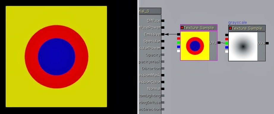
If you plug a black and white map (let's call it texture B) straight into the UV coordinates of another texture (let's call it texture A), it will remap A according to the information on texture B.

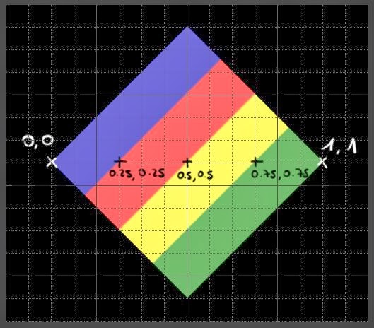
A white pixel on texture B will go pick the colour of texture A at 1,1.
A mid grey pixel on texture B will go pick the colour of texture A at 0.5,0.5.
A black pixel on texture B will go pick the colour of texture A at 0,0.


Here's an example using our gradient:

The top stroke is white so it goes and pick some yellow, the bottom stroke is a 128 grey so it goes and pick some red and the black background picks some blue.


Exact same thing with a more complex texture this time:


Now, you might think there’s a catch. The gradient is horizontal but we're picking the colour in a diagonal. Sure but look, the values are still accurate.
  
Obviously, since a texture's got 2 directions, U and V, you can map each direction independently but it's more simply explained with 1 single channel.
In fact it can give you a bit of a headache trying to paint a map purposely. (This is experience talking.) Still, here's an example of the two channels remapped non-uniformly.

You don't really want to paint this by hand (Well maybe you do but I certainly don't), but this is really cool for automated systems.
Say in a skin shader for instance where, say the U is going to be your SSS gradient > getting red where the light goes through the skin (in texture B you'll have the SSS map in the R channel) while in the V you'll store a lighting gradient > the colour of skin in the shadow and in the light (here you'll feed in the lighting info from your level.)


Clamping your texture.

 Now one crucial thing to remember is to clamp your texture A (so it doesn’t wrap around the material which is the default behaviour).
 

This is how messed up it looks when texture A is wrapped:

While a clamped texture A looks like this:

However if the texture B you plug in does wrap, it's all good and you'll get no artifacts. No need to clamp it.


While we're here, quick digression. Do you know you can batch edit textures? (Well, not only textures but this what we're dealing with right now.) You could clamp a few textures all at once for instance.

Select a few, right clic and choose ‘properties’.


Linear textures.

We’ll also have to talk about linear vs Srgb real quick. You can read loads about it, I’ll only sum it up.

By default your textures are interpreted as Srgb, they get a 2.2 power applied to them so they look ok on our monitors (that’s because of the way monitors are built).
That's this tickbox here:

A texture that goes into the emissive or diffuse will need to be Srgb. (the ones you actually see)
Textures used for UV distortion, timings etc. should not be Srgb.

In theory at least.
That's if you need a precise result; for some noise distortions it might not matter so much to be fair. You might not need to duplicate all your textures to have one linear and one Srgb version.

If you do some kind of maths with it though, it's almost compulsory otherwise your results won't be accurate.

Here's a little demonstration.

The top texture is the original. By remapping it with a horizontal gradient we should just get the exact same result.

You can see how messed up the colour gradient gets when it's remapped with an srgb texture.
At the bottom, remapping with a linear texture is almost accurate. It's not exactly, but it's a matter of texture compression.


Texture compression.

The texture compression can become very visible in certain cases. You can have a read at this article to find out more about DXT compression.

DXT1 clearly shows compression artifacts:

 Grayscale is going to look much better but will be loads more expensive in memory.


Now, if you need a really clean result your best option is to use maths. Do you remember the Pythagorean theorem ? That’s what we need.
It says that the square of the hypotenuse (the side opposite the right angle) is equal to the sum of the squares of the two other sides.
a² + b² = c²


a and b are basically our pixel coordinates.
The length of the hypotenuse is going to give us the colour value of our pixel.
The closer it is to the centre, the shorter the length of the hypotenuse, and the darker the colour. As you move away from the centre you move from black to white, and tada, you get a radial gradient.


We subtract 0.5 to the texture coordinates node to bring the gradient to the centre. (You can enter other values, that’ll shift the centre.)

We extract the U and V coordinated (a and b in the theorem) using a component mask, square them, and add them together (You could use the exponent node but I used a multiply in that case so the material looks less cluttered. It just looks more simple visually.)
That’s a² + b² done.

You than square root it and you’ve got the value of c, the hypotenuse. Now you still need to divide the result by 0.5 to bring it back to the range of our texture coordinates.
When you divide by 0.5, 1 is on the sides of the material.
When you divide by 0.7071 (the cosine of 45), 1 is in the corners of the material.

That was the slightly longer version to show where that comes from, but you can replace the whole a² + b² section by a dotproduct.


The fun part.

(at last.)

The idea is to create a sort of an animated warp. We start with a texture with multiple gradients. Since we’ll animated it and make it warp around, this one shouldn’t be clamped.
The setting is the same as just before, but this time we’ll add a panner to make the texture move outwards.


 It looks too clean though. This setup is bound to make perfect circles since the pixel sampled is exactly the same all around. However, we can still add some noise to it.

So. All that radial gradient coordinates business is somehow just like a texture coordinate node: it tells you what your coordinates are. And same as simple texture coordinates you can add some offset to it, so that’s what is happening there. Simply panning a texture, multiplying it by a small value to reduce its influence and adding to the radial coordinates. 


It doesn’t look that convincing just like this but you could make the gradients less contrasted, use this as a mask, even add the whole thing to another texture UV coordinates for that matter.

I used that base to create the warpy glow around the masks pickup in Enslaved.


Quick recap:
  • Import your gradients as thin rectangles.
  • Clamp them when you want to remap them with a texture that doesn't wrap.
  • Use linear textures to remap (for accurate results).
  • Think about your compression 
  • Play around and have fun