I originally made this set up for a quick and dirty rain test. The rain was one big gpu particles emitter, no collisions, no nothing, so it was raining indoors.
The dirty approach to solve this issue was to make the rain transparent in the indoors volume.
The idea is to define the range which will remain white in each of the x, y and z axis and then multiply everything together to define the volume.
Defining the range per axis.
We're using a set up I've already described so I'll be quick there. (Told you I liked to use it all over the place.)
For each axis, we're remapping a range of values to a gradient from 0 to 1, then we will also ceil it and clamp the result.
We do it for the min, and we end up with 0 below the minimum and 1 until the infinite.
We
do the same thing again but we invert the values (min becomes max and
vice versa) so we end up with 0 above the max and an infinite 1 in the
negative direction.
Finally, we multiply the min and the max.
Now our range is 1 and any value above or below is 0.
Doing it the proper way.
That was the simple way of explaining it and the way I actually created the original material, but while I recreated it for this post I realised the set up could be simplified a lot with a decent saving on instructions count (34 instead of 43).
The idea is the same but we're dealing with all 3 channels at the same time for the mins on the one hand and on the other hand for the maxs.
After we've been through the value (world position in this case) minus min / divided by max minus min / ceil / constant clamp, we separate the 3 channels (with a component mask) and multiply them by one another.
We end up for the mins with 0 below the min and an infinite 1 along the positive of each axis, and for the maxs with 0 above the max and an infinite 1 along the negative of each axis.
Multiply mins and maxs together and you've got your volume.
In the following video, I'm moving the emitter around so you can see that the coordinates are in world space. (I applied that material to a bunch of simple sprites.)
We could also make them local space if we'd fancy that, by simply subtracting the object position to the world position.
Nice and easy today.
We're starting off with this texture, which is clamped.
When you scale it down (= tile it at a value greater than 1) it moves to the upper left corner. That's because 0,0 is in this corner.
With the following setup, you'll scale the texture from the visual centre of the material:
What is happening exactly?
First we subtract 0.5,0.5 to our texture coordinates. We're shifting the texture and bringing 0,0 to the centre.
Then we scale it.
Finally we add 0.5, 0.5 to bring the texture back to the original position. Simple :)
This was used in Enslaved in the dragonfly scan post process. The values subtracted/added back were exposed and so was the scaling factor, so that the glowy reticle could be animated in matinee.
A screenshot won't tell you much about it but you can see in it in my enslaved showreel from 2:00. It's super short but I couldn't find any specific youtube video. Well, gotta play Enslaved to see it at its best ;)
Now, that was a bit short so let's talk some more.
When reducing the size of a clamped texture a lot, you can come across mipmap artifacts.
One fix is the Preserve Border option.
The tooltip says: ‘If true, the color border pixels are preserved by mipmap generation. One flag per color channel.’
Now the result is much better, but we can still see some artifacts.
Here is the texture I created. The last two pixels are plain black but pixel 3 and 4 start to be white. The dxt compression is done with blocks of 4 pixels so since I've got both black and white in a 4 pixel group, my mipmaps get messed up.
I reimported the texture and made sure I've got a clean 4 pixels border. Even with preserve border off, I don't get any artifacts.
They will appear at a lower mipmap though, but won't ever appear with a correct border and the preserve border option.
Say you want to manually animate a flipbook in matinee.
Here's a very simplified setup for it. The downside is: is has to be one single row but you can modify the amount of columns as you wish.
There could be less instructions but the idea is to make it easy to instance. In the material instance, you just have to modify the FramesAmount parameter and you can animate the FrameIndex parameter in matinee with everything working fine.
What's happening there?
You simple tile and shift your texture.
Tiling.
In this case, one tile is a forth of the texture size. So you divide 1 by the amount of horizontal frames in your texture and multiply only the U of your texture coordinates.
You've got the correct tile size.
Shifting.
To display the correct frame at the right moment, you'll just need to move the texture horizontally.
The amount by which you need to shift the texture to reach the next frame is one nth of your texture, n being th amount of horizontal frames. (4 in this case)
The FrameIndex value (animated from matinee) multiplies this to find how many times you need to shift it.
The floor node is there to ensure you only display full frames.
Since the frame index is floored, your index will be starting at 0, remember this when you control the value in matinee. To animate a four-frames texture, the value will have to interpolate between 0 and 3. (If your texture is set to wrap, a FrameIndex of four will get you back to displaying frame 0.)
Simple.
Not super clean or flexible but definitely super simple.
Quick look at vector graphics textures in after effect.
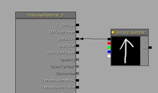
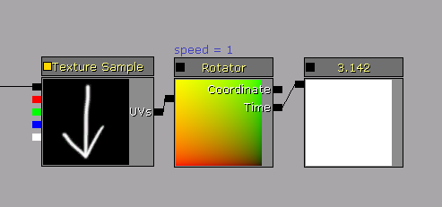
Fixed rotator.
How to rotate a texture by a certain fixed angle?
Just
input a constant value in the time pin of your rotator. The constant
value is like saying ‘this is where the rotator would get you in that
much time’. (I mean, not technically since the unit is not seconds but
it's sort of a way of seeing it.)
What to expect from
that value? First thing, set your rotator speed to 1. Then you have to
know that unreal uses radians as a rotation unit.
180 degrees = π (pi, the maths symbol equal to 3.14159 and so on).
Therefore, 90 degrees is going to be π / 2.
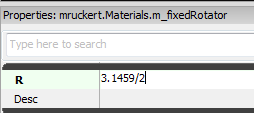
Good thing to know: you can do maths in input fields. In your constant input, you can simply type in 3.14159/2.
Usage.
You could use a fixed rotator to represent a
circular gauge for instance. Most likely, the gameplay code is going to
provide you with some normalized parameter. (Frankly that’s the best
option. Sure modifying the value to fill your needs will add a few
instructions but it gives you the flexibility to easily do anything you
want with it, rather than having to go bug a coder so he changes the
value he's hard coded for you.)
Modify the input to
the range you are interested in (say 0 to 90 degrees), plug it into the
rotator, and then into a mask that multiplies your gauge.
You’ll
notice that I’ve just multiplied my normalised value; since my min is
0, I don’t need to use a lerp which would add more instructions for the
same result.
Fixed rotator with steps.
We can go one step further.
In Enslaved, Trip has an emp gauge which recharges over time and is split in several chunks which appear one at a time.
I
used a similar setting, with a rotating mask that multiplied my
texture, only this time the rotation value had to be contained until it
reached the next step.
In the following example our gauge value is at 0.5, that's half filled. The gauge is split into 5 chunks, so each step is 0.2.
We check: our many steps are there in our current value ? That's 0.5 / 0.2 = 2.5. We're only interested in full steps so we floor it.
We've then got two full steps, the step size is 0.2 that's 0.2*2, our output value is 0.4.
The
floor node is going to keep the value contained at 0.4 until the next
integer is reached. When we get to 3 full steps, the output will
suddenly jump to 0.6 and so on.
The input value is divided by your step size, floored and then multiplied by your step size.
Credit for this little setup goes to Gavin Costello, currently Lead Programmer at Ninja Theory and full time graphics programming genius.
Vector graphics textures in after effect.
I've got a
thing for after effects in general, and I find it excellent for vector
graphics in particular. It's very flexible, the textures are easily
scaled and iterated. Illustrator could do the same but with after
effects you can also animate everything for previs and/or flipbook
generation. (Which is exactly how I worked during Enslaved. My previs
and textures were the same assets.)
Here's the way I made the previous gauge for instance, using shape layers:
2
ellipses, 6 rectangles, a subtract merge to cut out the inner circle
and the rectangles, another rectangle and an intersect merge to extract
the bottom left quarter. And finally a white fill of course.
I
like to use expressions even with these sort of very simple shapes. It
is a small time saver as you make the texture and might be a massive one
along the project as you iterate on your texture.
Right
there for instance, I link the anchor point to my rectangle size for
the anchor to be at the end of the rectangle rather than in the default
centre. Sure I could have done it by hand but I find it better when
automated. I was a bit lasy in this case so I stopped there but if I had
created this texture for production, I would have also:
linked the size of every rectangle to the first rectangle (or even neater, to a slider control)
linked the rotation of every rectangle to a slider control (and multiplied it by 2, 3, 4 etc. for each next rectangle)
and maybe controlled the radius of each ellipse from a slider
parameter too, just so as to modify everything for one single place and
not have to open up the content properties
You can
already find this elsewhere on the internet but this post just means there’ll
be one more source that might help someone find the info. (Plus it’s a note to
self.)
So. I wanted two things to get done in notepad ++:
Modify an
existing colour theme.
Set the
default language to C++ for certain files types.
Modify an
existing colour theme.
Go to the
Settings menu > Style Configurator.
In the
upper part of the window, choose a selected theme.
Good for
you if you find one that suits you entirely. I generally like the one named
‘Choco’ but I don’t like the selected text colour which I find not visible
enough.
To personalize a theme, go find
your themes folder within your Notepad++ files. (Mine is
C:\Program Files (x86)\Notepad++\themes).
Copy your favourite
theme and rename it. Now you’d think that you could edit your newly created
theme from the Style Configurator and go Global Styles > Selected text
colour and change the background colour. So did I.
Yeah, but
for some reason this is only going to last for your current session and next
time you restart, your changes will be lost. You need to edit your theme’s text
file directly. Open it, search for ‘Selected text colour’ and change the
background colour to your desired value.
Set the
default language to C++ for certain files types.
Go to the
Settings menu > Style Configurator.
Choose the
language you want to add extensions to from the left hand side list then add
the extensions in the ‘User ext’ box:
I said that ‘At the bottom, remapping with a linear texture is almost accurate. It's not exactly, but it's a matter of texture compression.’
I WAS WRONG. Systematically blaming texture compression is too easy.A flow in my photoshop knowledge was to be blamed, and I found out about that thanks to Simon Trümpler in this post. (We will be getting back to this post some time soon).
When you create a gradient in photoshop, there's a property called smoothness that you need to set to 0 if you want the interpolation between your gradient stops to be linear. This is what was truely messing up my gradient.
An easy way to double check that this is correct in photoshop is to create a 256 texture and compare the mouse pointer position with the brightness value.
At 48 in position, the 0% smoothness gradient = 48
while the 100% smoothness gradient = 36
At 173 in position, the 0% smoothness gradient = 174
while the 100% smoothness gradient = 184
At 255 in position, the 0% smoothness gradient = 255
while the 100% smoothness gradient = 255
At 100 % smoothness, the values get accurate in certain positions (near the stops and midpoints) but they shift in between.
The 0 % smoothness ramp is not fully accurate, you might be a pixel off sometimes but overall it's pretty good.
And this how it verifies in the udk:
(don't forget that the srgb option needs to be false in your gradients textures)