That was meant to be a quick one, fun and visual, but I realized I'll need to explain a few things before I get to the fun part.
I want to get there: sort of a bendy animated warp.
But first we will talk about :
- importing gradient textures
- remapping a texture using another texture
- linear textures
- texture compression
- trigonometry
Importing gradient textures.
The texture we are going to remap is a horizontal ramp, so let's talk quickly about creating the right texture to import.
When you're using a vertical or horizontal ramp, do not import a square texture, that's pointless! Make a thin strip of it, which will be stretched in the material.
Let's take our horizontal ramp. You're not loosing definition by stretching the texture vertically since the value is the same on every pixel aligned vertically. Just make a texture 2 pixel high, or maybe 4 if you're a bit short-sighted.
This is what the texture looks like in generic browser:
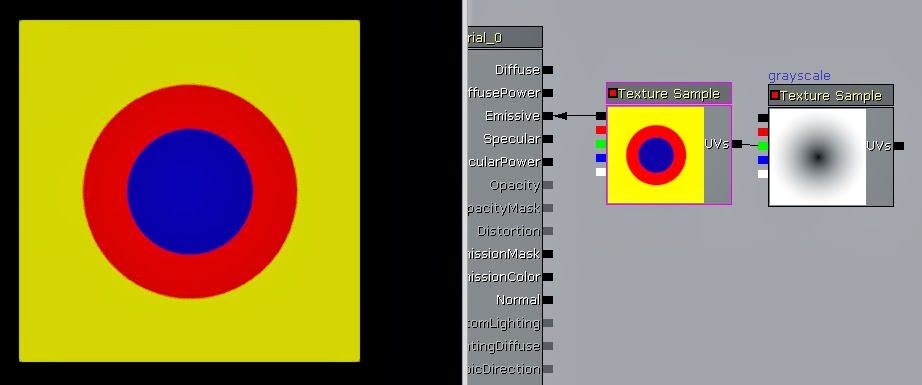
This is what it looks like in the material:
Remapping a texture using another texture.
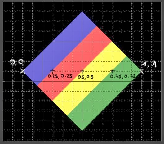
This is super common for people used to work with materials but not everybody is so I'll explain it briefly.If you plug a black and white map (let's call it texture B) straight into the UV coordinates of another texture (let's call it texture A), it will remap A according to the information on texture B.
A white pixel on texture B will go pick the colour of texture A at 1,1.
A mid grey pixel on texture B will go pick the colour of texture A at 0.5,0.5.
A black pixel on texture B will go pick the colour of texture A at 0,0.

The top stroke is white so it goes and pick some yellow, the bottom stroke is a 128 grey so it goes and pick some red and the black background picks some blue.
Exact same thing with a more complex texture this time:
Now, you
might think there’s a catch. The gradient is horizontal but we're picking the
colour in a diagonal. Sure but look, the values are still accurate.
In fact it can give you a bit of a headache trying to paint a map purposely. (This is experience talking.) Still, here's an example of the two channels remapped non-uniformly.
You don't really want to paint this by hand (Well maybe you do but I certainly don't), but this is really cool for automated systems.
Say in a skin shader for instance where, say the U is going to be your SSS gradient > getting red where the light goes through the skin (in texture B you'll have the SSS map in the R channel) while in the V you'll store a lighting gradient > the colour of skin in the shadow and in the light (here you'll feed in the lighting info from your level.)
Clamping your texture.
Now one
crucial thing to remember is to clamp your texture A (so it doesn’t wrap around
the material which is the default behaviour).
This is how messed up it looks when texture A is wrapped:
While a clamped texture A looks like this:
However if the texture B you plug in does wrap, it's all good and you'll get no artifacts. No need to clamp it.
While we're here, quick digression. Do you know you can batch edit textures? (Well, not only textures but this what we're dealing with right now.) You could clamp a few textures all at once for instance.
Select a few, right clic and choose ‘properties’.

Linear textures.
We’ll also
have to talk about linear vs Srgb real quick. You can read loads about it, I’ll
only sum it up.
By default
your textures are interpreted as Srgb, they get a 2.2 power applied to them so they
look ok on our monitors (that’s because of the way monitors are built).
That's this tickbox here:A texture that goes into the emissive or diffuse will need to be Srgb. (the ones you actually see)
Textures used for UV distortion, timings etc. should not be Srgb.
In theory at least.
That's if you need a precise result; for some noise distortions it might not matter so much to be fair. You might not need to duplicate all your textures to have one linear and one Srgb version.
If you do some kind of maths with it though, it's almost compulsory otherwise your results won't be accurate.
Here's a little demonstration.
You can see how messed up the colour gradient gets when it's remapped with an srgb texture.
At the bottom, remapping with a linear texture is almost accurate. It's not exactly, but it's a matter of texture compression.
Texture compression.
The texture compression can become very visible in certain cases. You can have a read at this article to find out more about DXT compression.DXT1 clearly shows compression artifacts:
Grayscale is going to look much better but will be loads more expensive in memory.
Now, if you need a really clean
result your best option is to use maths. Do you remember the Pythagorean
theorem ? That’s what we need.
It says that the square of the hypotenuse (the side opposite the right angle) is equal to the sum of the squares of the two other sides.
a² + b² = c²
a and b are basically our pixel coordinates.
The length of the hypotenuse is going to give us the colour value of our pixel.
The closer it is to the centre, the shorter the length of the hypotenuse, and the darker the colour. As you move away from the centre you move from black to white, and tada, you get a radial gradient.
We subtract 0.5 to the texture
coordinates node to bring the gradient to the centre. (You can enter
other values, that’ll shift the centre.)
We extract the U and V
coordinated (a and b in the theorem) using a component mask, square
them, and add them together (You could use the exponent node but I used a
multiply in that case so the material looks less cluttered. It
just looks more simple visually.)
That’s a² + b² done.
You than square root it and
you’ve got the value of c, the hypotenuse. Now you still need to divide
the result by 0.5 to bring it back to the range of our texture
coordinates.
When you divide by 0.5, 1 is on the sides of the material.
When you divide by 0.7071 (the cosine of 45), 1 is in the corners of the material.
That was the slightly longer version to show where that comes from, but you can replace the whole a² + b² section by a dotproduct.
That was the slightly longer version to show where that comes from, but you can replace the whole a² + b² section by a dotproduct.
The fun part.
(at last.)
The idea is
to create a sort of an animated warp. We start with a texture with multiple
gradients. Since we’ll animated it and make it warp around, this one shouldn’t
be clamped.
The setting
is the same as just before, but this time we’ll add a panner to make the
texture move outwards.
It looks
too clean though. This setup is bound to make perfect circles since the pixel
sampled is exactly the same all around. However, we can still add some noise to
it.
So. All
that radial gradient coordinates business is somehow just like a texture
coordinate node: it tells you what your coordinates are. And same as simple
texture coordinates you can add some offset to it, so that’s what is happening
there. Simply panning a texture, multiplying it by a small value to reduce its
influence and adding to the radial coordinates.
It doesn’t
look that convincing just like this but you could make the gradients less
contrasted, use this as a mask, even add the whole thing to another texture UV
coordinates for that matter.
I used that
base to create the warpy glow around the masks pickup in Enslaved.
Quick recap:
- Import your gradients as thin rectangles.
- Clamp them when you want to remap them with a texture that doesn't wrap.
- Use linear textures to remap (for accurate results).
- Think about your compression
- Play around and have fun


No comments:
Post a Comment